Enforcing network traffic symmetry across stateful devices has long been the biggest routing challenge faced in our network. It is unquestionably the singular problem I have dedicated the most amount of brainstorming, whiteboarding, and testing to. In this blog I share the problem, how it relates to our network, and the theory and solution that we use to solve it. This blog assumes the reader has a strong foundation in BGP design and behavior for a full understanding of the theory and solution.
Traffic Symmetry
In many networks, asymmetry of traffic can be acceptable, provided it does not negatively affect the reliability of the traffic flow. Routers generally do not function as stateful devices — they do not require establishing and maintaining a connection that must handle both sides of a bidirectional traffic flow. However, firewalls, load balancers, and many security devices generally are stateful — they must observe the traffic flow in both directions. It should be intuitive that any device responsible for inspecting traffic, and not just forwarding traffic, would have this requirement. In a large disperse network that handles hundreds of stateful devices, the challenge rests on engineering the routing to ensure that any traffic flow traverses the same stateful device(s) bidirectionally. This challenge may be simple when stateful devices are placed at points in the network where traffic is naturally funneled, such as the ingress point to a local network, but may be very difficult when those devices are instead distributed across centralized locations.
Our Network
To better frame the problem as it relates to our network, it is helpful to provide an overview of our network design. Our network consolidated all network security and inspection into approximately a dozen centralized locations across the United States, while processing traffic originating at hundreds of other locations. We refer to these centralized security/inspection locations as stacks. They are a collection of routers, firewalls, switches, load balancers, passive and active inspection devices, and monitoring tools. These stacks also serve as the ingress/egress point for all traffic entering or exiting our network perimeter. Security is layered into tiers, where traffic flows often require traversing several sets of security devices when communicating between different organizations, each of whom control the security policy in their routing domain. Each stack provides redundancy within itself, as well as redundancy in predefined failover orders, such that any traffic pattern should have N+1 redundancy within a single stack, and N+2 redundancy across different stacks. In this model, every stack and edge location can be said to have a distinct primary, secondary, and tertiary stack for processing traffic.
All edge locations on the network are typically served by a single pair of edge routers with a L2 campus infrastructure.
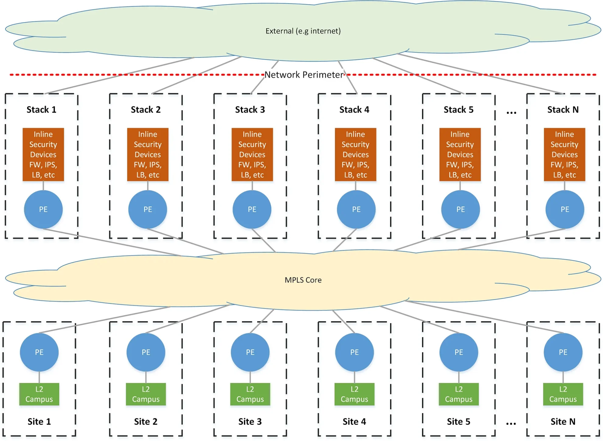
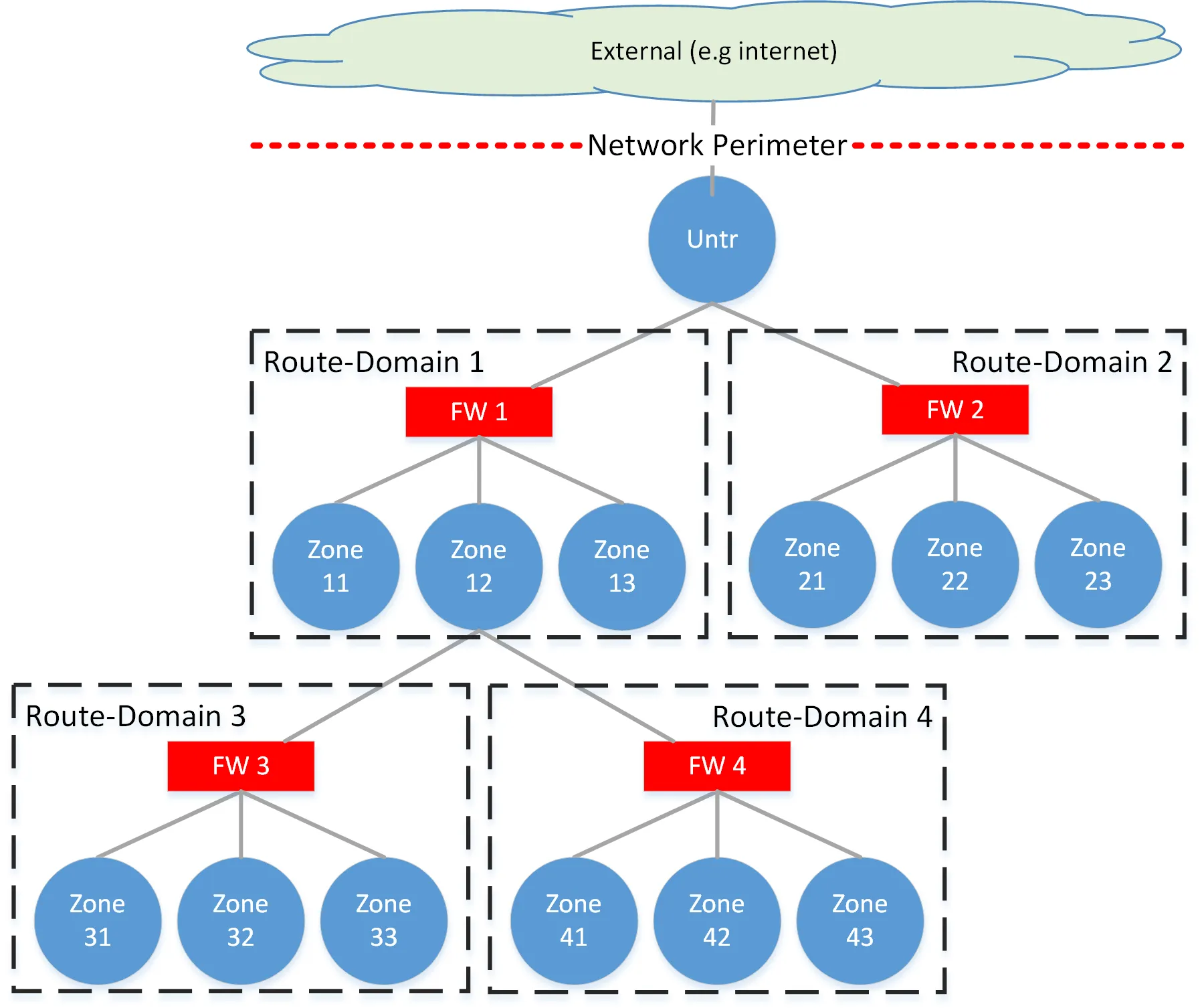
All locations on the network connect to an MPLS network and exchange L3 routing information in BGP via VPNv4/VPNv6. Every security zone on the network exists as an isolated forwarding domain that must traverse one or more security tiers to communicate outside of that zone. These are enforced by strictly segregated L3VPNs across the MPLS core, VRFs on routing devices, VLANs on switches, and ultimately correspond to a unique zone on a firewall, the sum of which we refer to as a routing-domain.
The routing-domains form the discrete components of the tiered architecture, where an upper tier may belong to a large entity who broadly controls the security policy for the entire organization at the network perimeter, while a lower tier may belong to a subdivision of that organization, responsible only for their piece of the network, but still nested within the organization as a whole.
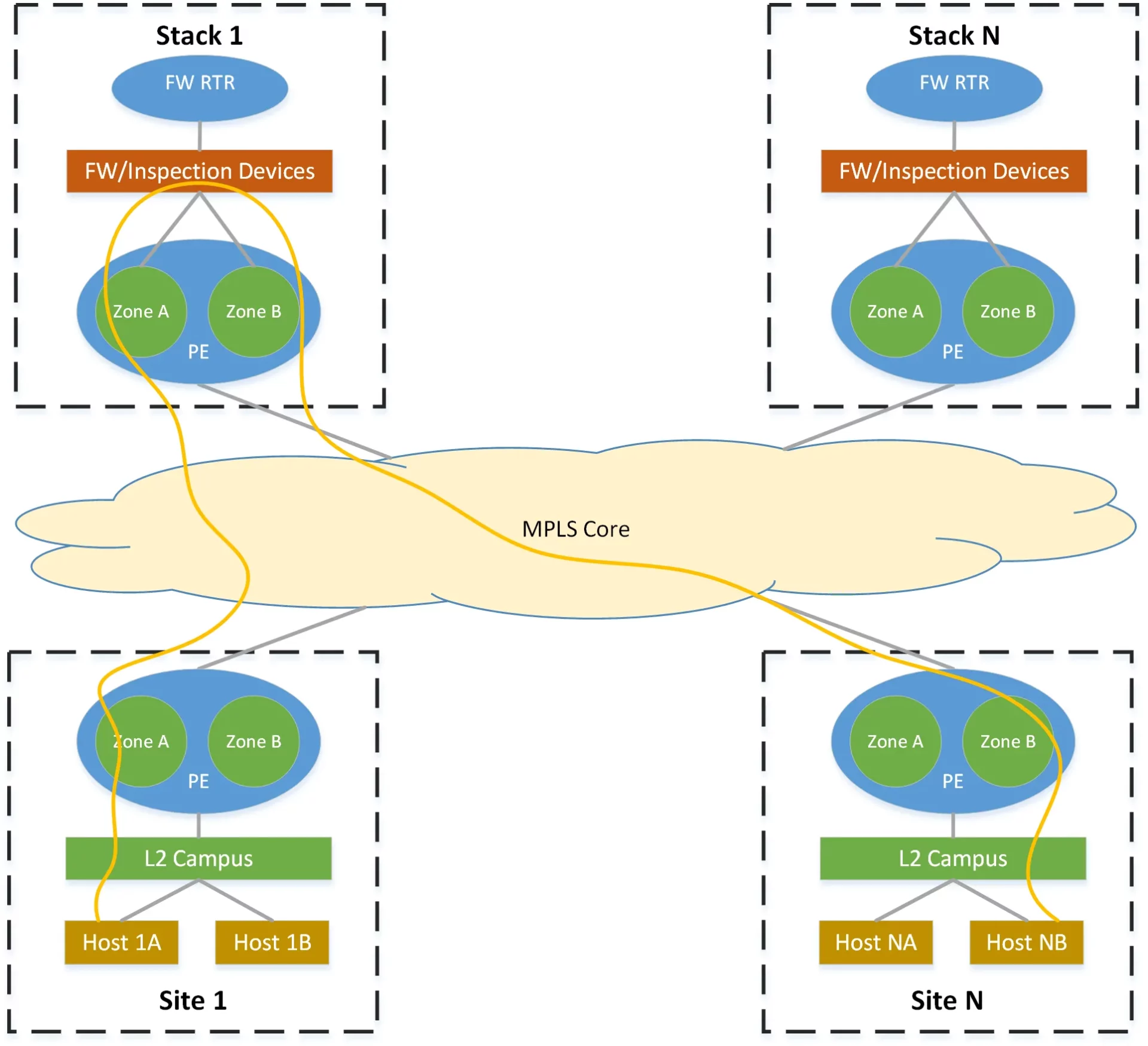
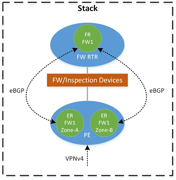
All intra-zone traffic routes directly while all inter-zone traffic must route through some portion of a stack — at a minimum across the FW within the zone’s routing domain. Routing information between zones within a stack is exchanged via eBGP, directly from each VRF on the edge routers to a control-plane-only router that we call the firewall-router. This router effectively shadows each firewall context and provides the routing functionality that could otherwise be provided by the firewall itself.
Requirements
The ultimate goal in developing our solution is that any traffic flow between hosts in different zones takes a symmetric path through the stacks, subject to the following requirements:
- Signaled in BGP — the routing logic must be enforced and signaled by BGP and without maintaining knowledge of specific prefixes (e.g. no policy-based-routing based on prefix lists).
- Redundancy — minimum N+2 redundancy across stacks must be provided for any traffic flow.
- Predictable/Optimal pathing — a traffic flow should always take a predictable and optimal path. These paths should be predetermined based on the geographic proximity of a network to a stack.
Theory
To better understand the logic behind how we solve this problem, I present the theory we use on how to classify and frame routing decisions within this environment.
Note: A number of unique terms to describe certain routing behaviors are defined and used in this section, often italicized, which should not be mistaken as belonging to the general network engineering lexicon nor any industry standard.
Source/Destination-Following
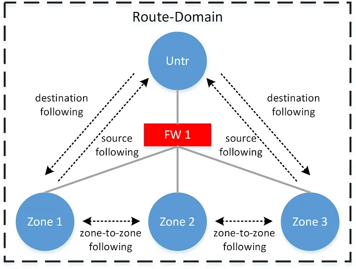
Source-following and destination-following are a pair of terms we coined to describe the two fundamental options for choosing a stack to route traffic through. In source-following, traffic to a destination follows the stack nearest to the source — but more accurately, the stack nearest the device forwarding the traffic. In destination-following, traffic to a destination follows the stack nearest to the destination. It should be apparent that using the same option bidirectionally results in asymmetry through the stacks. However, using the opposite technique on each side of the flow results in symmetry through a single stack.
This logic is implemented by tagging prefixes with communities indicating both their proximity to, and advertisement through, a particular stack. We then use these communities in policy to set appropriate metrics.
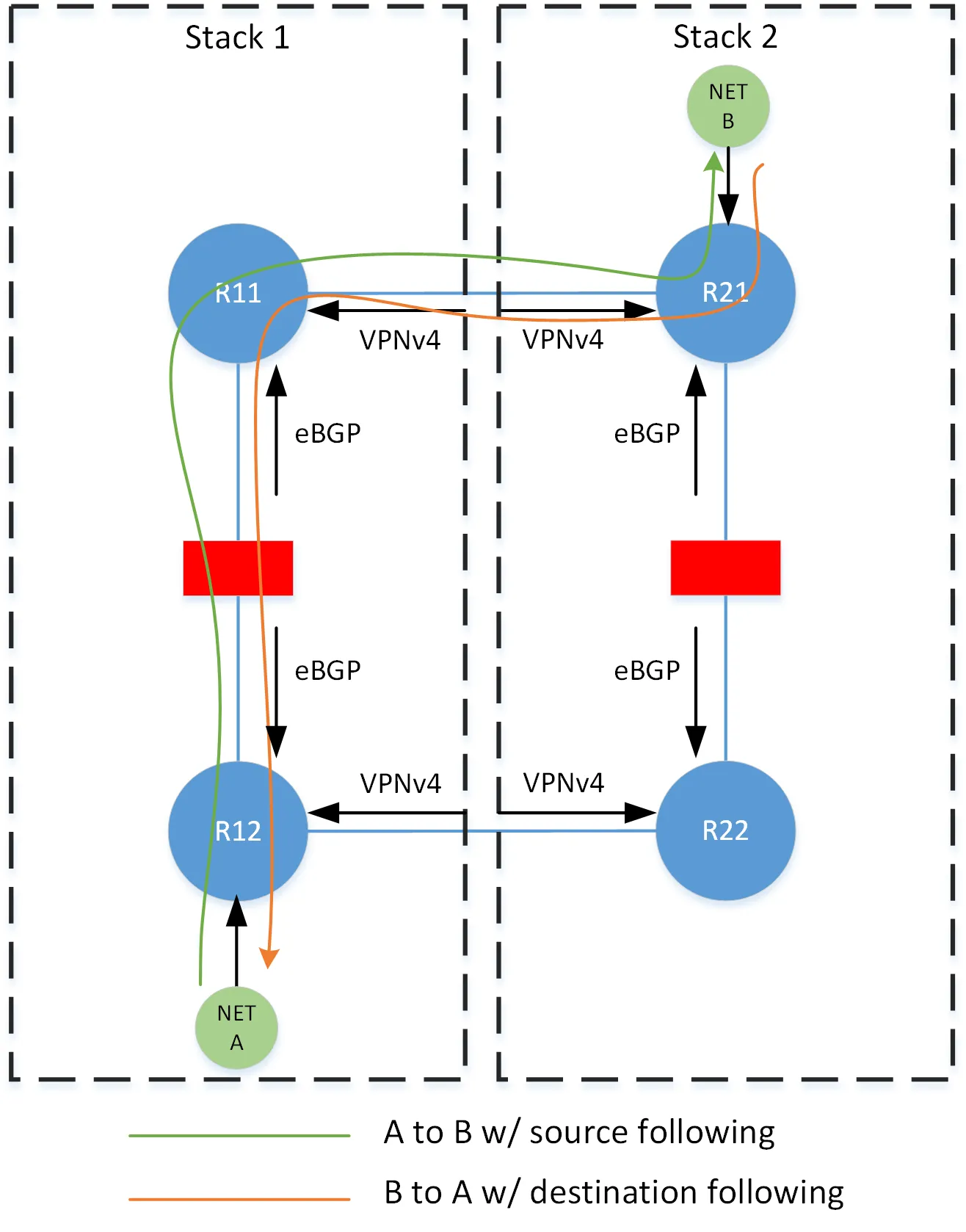
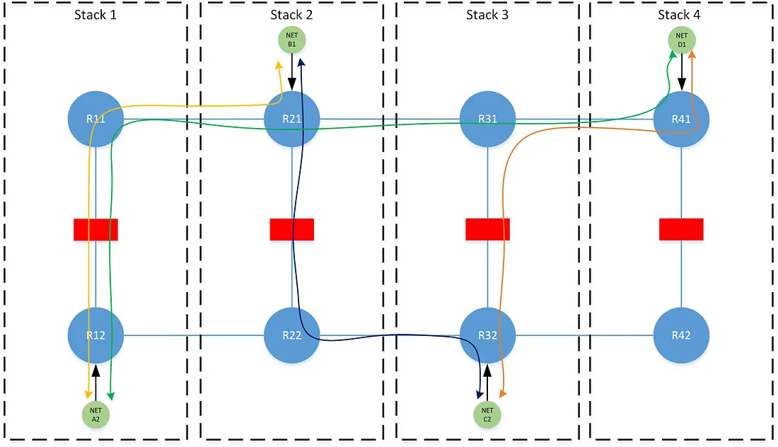
Consider for the following examples, the network is composed of 4 stacks with N+1 redundancy, and where 1/2 and 3/4 form redundancy groups (i.e 1 is secondary to 2, and 2 is secondary is 1). Each Rx, represents a specific forwarding table (i.e. VRF) on the edge routers at the stack.
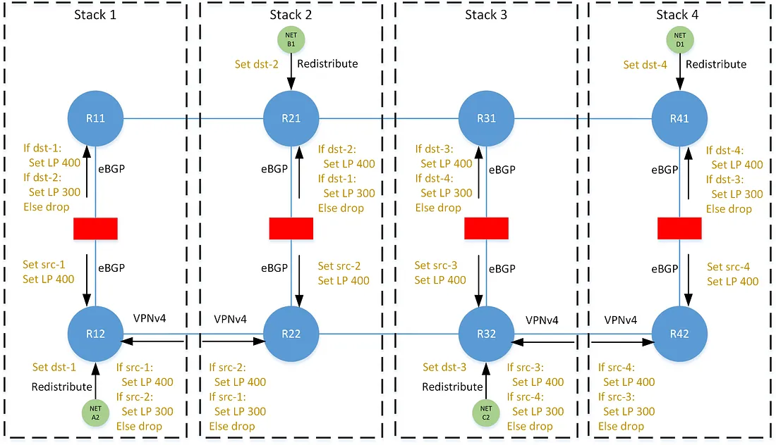
In destination-following, each prefix is tagged with the dst-x community when originated into BGP, where x is an identifier for the stack. Policies on the north/south eBGP neighbors within the stack set a local-preference of 400 for paths tagged with the dst-x community that corresponds to its local stack, and a local-preference of 300 for paths that correspond to its secondary stack. The preferences are unmodified as they are advertised east/west across the VPNv4 mesh, and thus all tables on that horizontal plane share the same perspective on any prefix — each agree on the same best path for any prefix.
In source-following, each path is tagged with the src-x community when advertised north/south through the stack. Policies on the north/south eBGP neighbors set a local-preference of 400 for all paths. The east/west VPNv4 neighbors set a local-preference of 400 for paths corresponding to its local stack, and 300 for paths corresponding to its secondary stack, as indicated by the src-x community. In this case, all tables on the horizontal plane have a different perspective on the best path for any prefix.
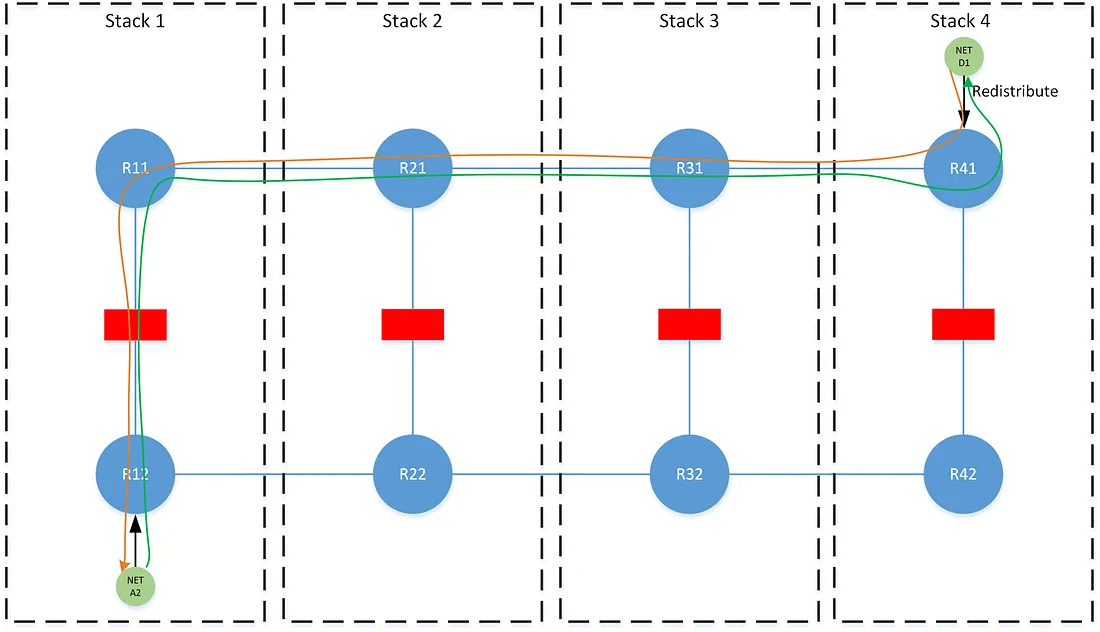
In this scenario, the best path at R12 to network D1 is the LP 400 path learned through the stack from R11, and the best path at R11 is the LP 400 path learned laterally from R41. The best path at R41 to prefix A2 is the LP 400 path learned laterally from R11, and at R11 is the LP 400 path learned through the stack from R12.
Source/Destination-Following Control-Plane Overhead
It may be intuitive that that following an anycasted prefix (e.g. a default route), where that prefix may originate equally at all stacks, would be consistent with the method of source-following. Indeed we are required to follow the stack of the source in this case — an anycast route must never be originated on the side that uses destination-following, as this would result in bi-directional source-following. In a similar fashion, source-following is conducive to the use of expansive aggregate routes or supernets, without concern to the originating stack of a contributor. This allows for a notable reduction in control-plane overhead. For destination-following, aggregation can only be accomplished as well as a contributing and suppressed prefix matches the designated origin of the aggregate route.
Tiered Source/Destination-Following
When expanding the source/destination-following concept to multiple tiers, additional logic is required to continue to enforce symmetry during a failure of individual tiers within a stack. Consider the below scenario where there is a failure at the lower tier at stack-1. The traffic flows asymmetric through the upper tier due to a shift in perspective when traffic from network A2 fails over to stack-2. The network A2 prefix continues to be shared laterally across the Rx2 tables above the failure, and then advertised through the upper tier at all stacks. The destination-following logic would dictate that the best path for prefix A2 on all Rx1 tables is the LP 400 path learned laterally from R11 on stack-1. However during the failure event, traffic from network A2 would move laterally around the failure up through stack-2 to R22. At this point, the traffic must continue to follow stack-2’s perspective on how to reach network D1, which is to follow the path from R21 up the stack.
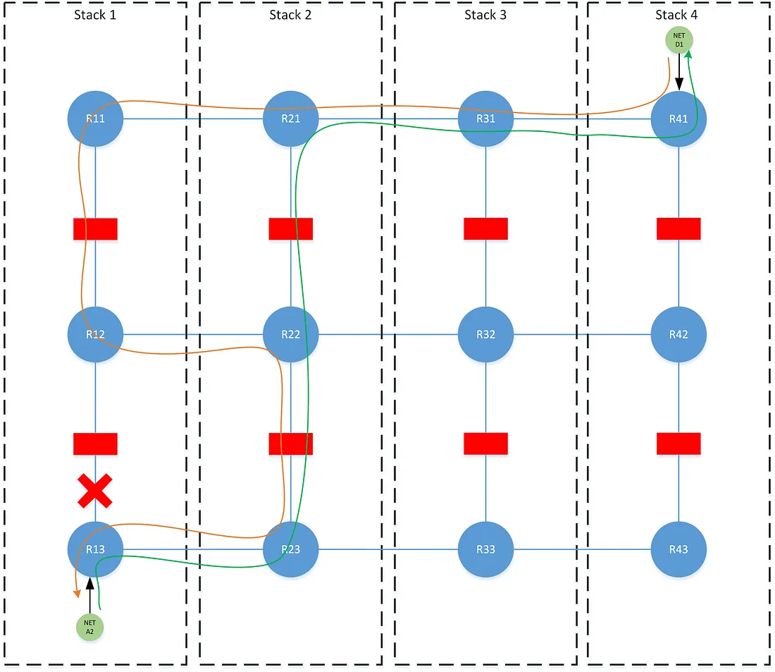
This problem introduces a pair of techniques that we call source-shifting and destination-shifting, where the src-x and dst-x communities are rewritten as a path traverses a tier. In destination-shifting, every stack in the prefix’s failover order rewrites the path’s existing dst-x community with the local dst-x community as the path is advertised across a tier. In source-shifting every stack rewrites the existing src-x community with the local src-x community as the path is advertised across a tier.
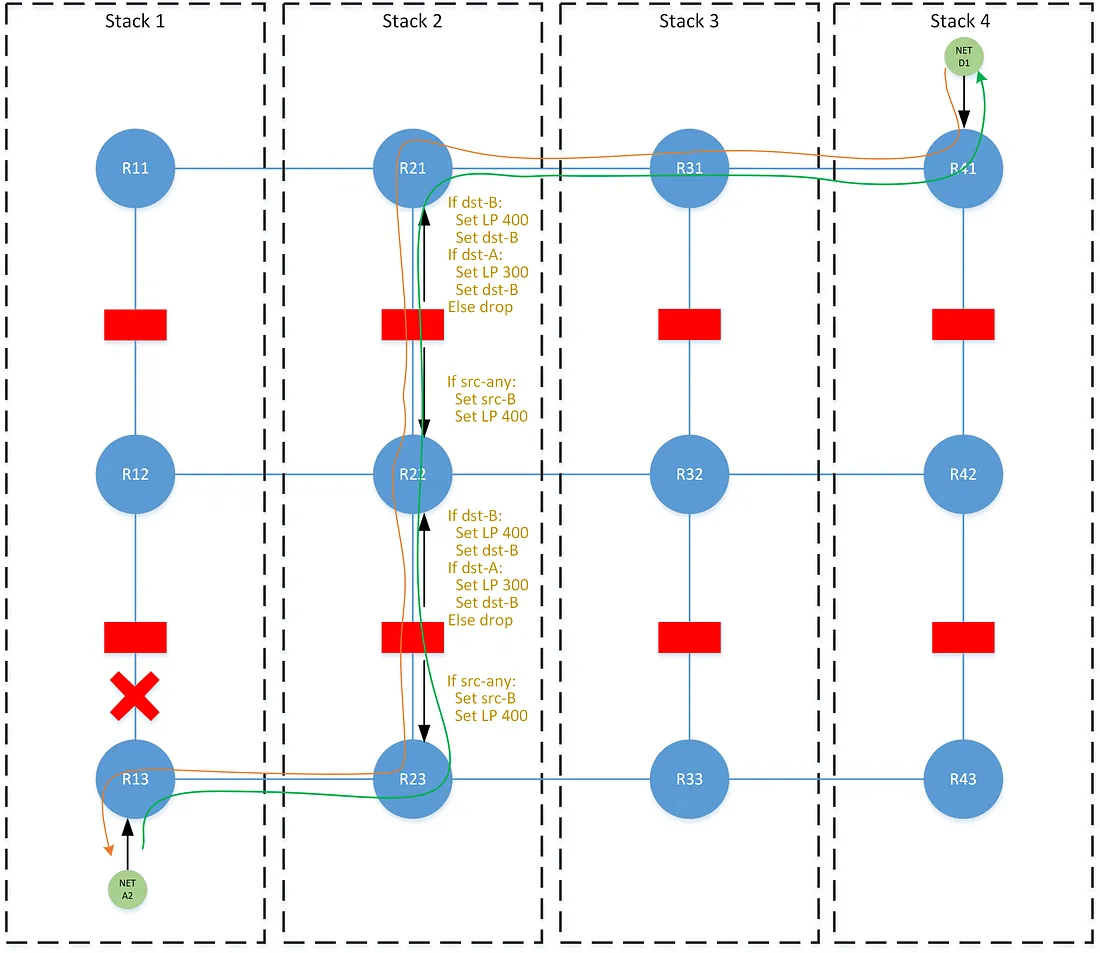
The destination-shifting technique relies on a concept that we call lateral-blocking, where paths learned laterally may block paths learned with different attributes across the stack. This, of course, is just standard BGP best-path selection behavior, but we highlight it to stress that we utilize path-selection for more than the basic purpose of influencing the forwarding table. We use it to signal information (e.g. network failures) carried in path-attributes, even in cases where the selection of one path over another has zero effect on the forwarding table. This is shown more clearly in the following sections.
In the non-failure scenario, the path for network A2 is rewritten with the local dst-x community across each stack in the failover order. The path learned laterally from R12 remains the best path on all Rx2, and is the one subsequently advertised to the next tier. In the failure scenario, the path with the rewritten dst-2 community onto R22 becomes the new best path. As that path is advertised through the upper tier, all Rx1 tables now see the path from R21 as the best path, and we achieve symmetry. The effect of this shifting behavior is that lower tier failures propagate up, causing traffic to shift to another stack across both tiers. However upper tier failures are masked, and traffic does not shift until reaching the tier that has failed.
Zone Directionality
These concepts apply well when there is a clear choice for determining which side utilizes source-following and which side utilizes destination-following. The natural direction in our network would simply be up/down the stack. Where down points towards lower tiers closer to the edge of user networks, while up points to the upper tiers towards the egress of our network perimeter. For many traffic flows, that distinction cannot easily be made, for example, between two zones that are neither up nor down from each other. This largely applies to traffic between different DMZs within the same routing-domain, and forms what we refer to as zone-to-zone routing. Moreover, as there may be many zones in the same routing-domain, they all must be consistent in determining a routing option.
The directionality problem can be solved by determining a predictable ordering of the stacks (e.g. stack-1 is of a lower order than stack-2, and stack-2 is of a lower order than stack-3, etc) where routing between two zones utilizes source-following from a zone at a lower ordered stack, and utilizes destination-following from a zone at the higher ordered stack. For the below example: traffic from network A2 to B1 should traverse stack-1, from A2 to D1 should traverse stack-1, from B1 to C2 should traverse stack-2, and from C2 to D1 should traverse stack-3.
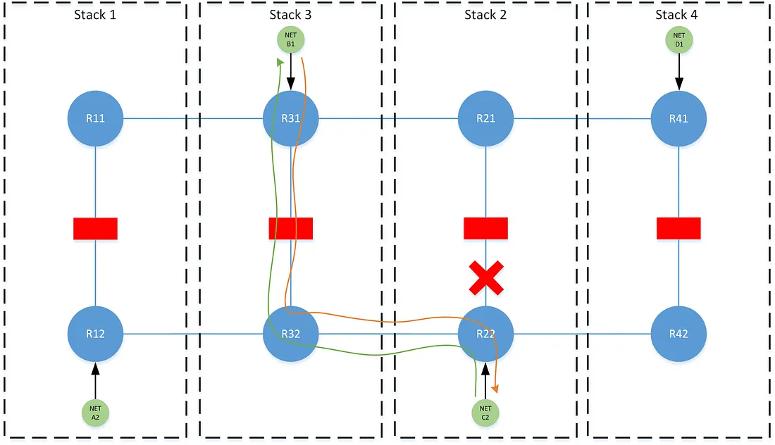
This logic however is slightly more nuanced, in that similar to the tiering problem, the perspective of each stack must be accounted for. In the following examples, note that stacks 2 and 3 have been flipped, such that 1/3 and 2/4 now form each redundancy group, but where the stack ordering of 1 < 2 < 3 < 4 remains the same.
Traffic between B1 and C2 would normally traverse stack-2, due to stack stack-2 being of a lower order than stack-3. During a failure at stack-2, R22 could not choose to traverse its secondary stack-4, since R42 will have a different (and unchanged by this failure) perspective that the best path to reach B1 is via the lower ordered stack-3 on R32.
This likewise applies in a dual-failure where both stack 2 and stack-3 have failed. Both R22 and R31 are forced to consider the perspective of their redundant stacks with respect to the best path, despite the fact that the traffic now follows the failover-order of the higher ordered stack as opposed to the failover-order of the lower ordered stack.
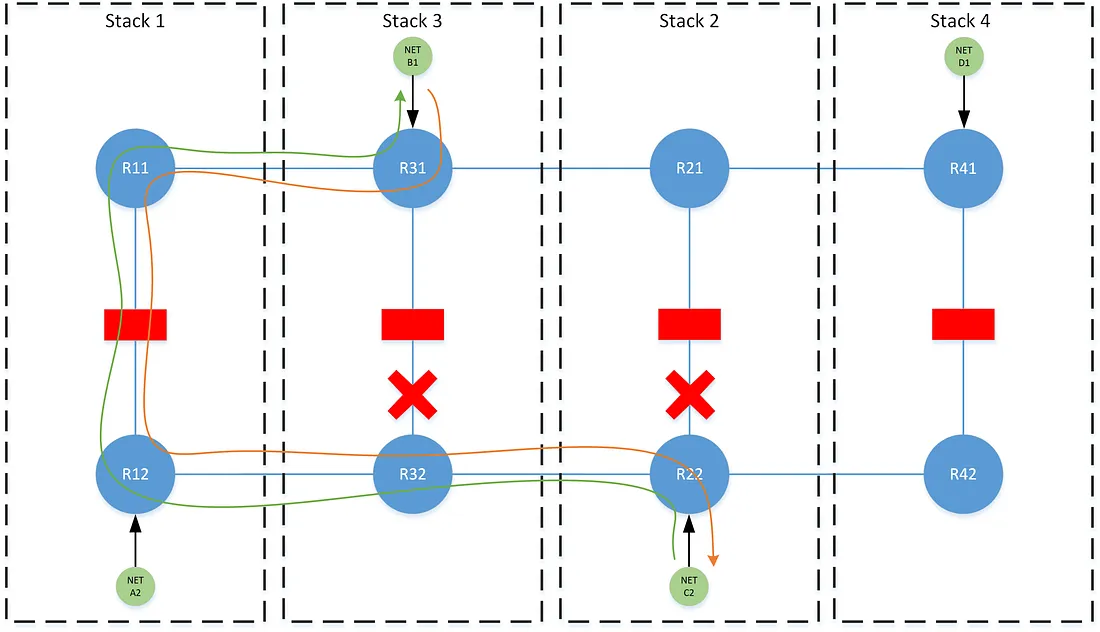
To achieve this, we preference paths as the combination of both the stack ordering and the advertising stack’s position in the path’s failover order (i.e. primary vs secondary). The rule being: when routing between two networks, choose the highest failover position (e.g pri is better than sec) and then lowest ordered stack between them.
To implement, we use a third helper failover community for each level of redundancy: failover-pri, failover-sec, etc. This community is applied when a path is advertised through any stack within the path’s failover order. For example, when network A2 is advertised through stack-1, it is tagged with failover-pri. When that prefix is advertised through stack-3 (keeping with the failover pairs from the previous example), it is tagged with failover-sec. When advertised through stack-2 or stack-4, no failover community is applied. This community is not fundamental, in that it can be derived from an existing pair of dst-x and src-x values, however the abstraction substantially reduces the verbosity of the policies that use it.
The failover community in conjunction with the src-x community signals the information needed to preference any path: which stack the path is being advertised from, and where in the failover order (pri/sec/etc) the stack belongs for that path. Illustrating the logic directly on the diagrams would be impractical, but a complete implementation is provided in the following sections. This preferencing logic is applied on both the eBGP peers through the stack and the lateral VPNv4 peers, where the paths are ordered from most preferred to least preferred as follows:
- From a stack lower or equal ordered to the primary and is the failover-primary for the path.
- From primary stack.
- From a stack higher ordered to the primary and is the failover-primary for the path.
- From a stack lower or equal ordered to the secondary and is the failover-secondary for the path.
- From secondary stack.
- From a stack higher ordered to the secondary and is the failover-secondary for the path.
… Each set of 3 terms repeat for the degree of stack redundancy required.
Zone-to-Zone Control-Plane Overhead
The zone-to-zone model, while flexible, comes at the worst case expense in control-plane utilization. Generally, every prefix originating in a zone must be installed in the forwarding table for every other zone. Unlike source/destination-following, the option to at least reduce the overhead from the source-following side, with a default route or broad aggregation, does not apply.
Tiered Zone-to-Zone
The zone-to-zone model nearly breaks down when it is attempted across multiple tiers. The same rules from the tiering section apply with the need for destination-shifting and source-shifting. The latter is by nature easy, as the only requirement is to implement a local rewrite of src-x. Destination-shifting is far more difficult, because it relies on lateral-blocking to force all stacks to agree on the same best-path. With zone-to-zone, the same lateral-blocking is not achieved — all routers on the same horizontal plane do not converge to the same best path. Without an agreement on the same best path, a dst-x rewrite would signal non-existent failures in accordance with the tiering logic.
If there is a solution to this problem purely in BGP policy, I have not discovered it, however a simple solution is taking advantage of another BGP feature here: add-path. The BGP add-path capability allows advertising and/or receiving multiple paths for the same prefix to/from a BGP neighbor. By implementing add-path send-only from R11 and R12 and add-path receive-only at the FW between them, we can finalize the necessary lateral-blocking at the mid-point, without affecting the forwarding decision made by the zone-to-zone logic. After lateral-blocking converges to a singular best path (i.e. from the stack with the highest failover position) at the FW, destination-shifting is implemented, and the paths are exported to R11/R12 with the desired attributes.
A hypothetical BGP feature that would allow for decoupling the selection of paths for advertisement from paths for RIB installation would allow for the cleanest solution to this.
Our Hybrid Solution
Our network had been through several iterations of solving this traffic problem. A variety of new requirements and unrealized failure scenarios caused us to rethink and redesign our solution. We ultimately settled on a hybrid model based on the principals described in the previous section.
While implementing a complete tiered zone-to-zone model across the entire network would provide the ultimate in flexibility and uniformity — the ideal one-size-fits-all approach — in practice and at our scale this would immediately crush and exhaust the control-plane resources on our network. The exponential growth of routes propagated in a complete zone-to-zone model would far exceed the resource capacity on our edge routers, which are hefty carrier grade routers as it is. Coupled with the fact that we do have some natural directionality to the network, we use the following hybrid approach where we partition each routing-domain on the network. This approach uses both the source/destination-following and tiered zone-to-zone models. The tiered portion of zone-to-zone is implemented in policy, but only used by exception.
For every routing-domain, we implement source/destination-following between the untrust zone and all other zones. The untrust zone is that which peers to any upper-tiers, and towards the network perimeter. Between the non-untrust zones, we implement zone-to-zone logic. When source-following to the untrust zone, we limit the advertised prefix to only the default route, and subsequently constrain the exponential growth of routes at each routing-domain boundary.
Recall from first section, that the peering design within a stack is represented as follows, where each zone in a particular routing-domain on the edge routers (coded as ER) peers to its corresponding table on the firewall-router (coded as an FR).
The following pseudo-code policies outline the logic used to implement this solution.
ER Redistribute — Unicast Prefix
Implemented during simple redistribution or origination of a network into BGP. We add only the the dst-x community, failover community, and set our default maximum local preference.
add community dest-<stack-id>
add community failover-pri
set local-pref 400
pass
ER Redistribute — Anycast Prefix
Implemented during redistribution or origination of an anycasted network into BGP (e.g a default route). We add only a special community anycast to signal it is an anycast network.
add community anycast
set local-pref 400
pass
ER-Untrust to FR Export
Implemented on the edge router when exporting paths from an untrust zone to the firewall-router. We pass only paths tagged with the anycast community, which should normally be only the default route.
if community matches anycast then
  pass
ER to FR Export
Implemented on the edge router when exporting paths from a non-untrust zone to the firewall-router. We pass only paths tagged with a failover community. In tiered zone-to-zone this limits the add-paths to only those necessary for lateral-blocking.
if community matches failover-all then
  pass
FR to ER Import
Implemented on the firewall-router when importing paths from any zone on the edge router. The policy completes the lateral-shifting needed in the tiered zone-to-zone model by preferencing the add-paths and which only applies to the paths from non-untrust zones.
if community matches failover-pri then
  set local-pref 400
elseif community matches failover-sec then
  set local-pref 300
elseif community matches failover-ter then
  set local-pref 200
pass
FR to ER Export
Implemented on the firewall-router when exporting paths to any zone on the edge router. The first section of the policy rewrites the src-x community needed for source-shifting. The next section simultaneously rewrites the dst-x community needed for destination-shifting, and rewrites the failover community needed for zone-to-zone logic.
delete community in src-all
add community src-<pri stack-id>
delete community in failover-all
if community matches <stack-id>-pri-dst then
  delete community in dst-all
  add community dst-<pri stack-id>
  add failover-pri
elseif community matches <stack-id>-sec-dst then
  delete community in dst-all
  add community dst-<pri stack-id>
  add failover-sec
elseif community matches <stack-id>-ter-dst then
  delete community in dst-all
  add community dst-<pri stack-id>
  add failover-ter
pass
ER-Untrust to FR Import
Implemented on the edge router when importing paths into an untrust zone from the firewall-router. The policy first deletes the src-x community set by the firewall-router in order to force the zone to bypass any zone-to-zone preferencing set by the VPNv4 policy and instead fall-through to destination-shifting. The preferences are set consistent with destination-shifting by matching on failover communities.
delete community in src-any
if community matches failover-pri then
  set local-pref 180
elseif community matches failover-sec then
  set local-pref 150
elseif community matches failover-ter then
  set local-pref 120
ER to FR Import
Implemented on the edge router when importing paths to a non-untrust zone from the firewall-router. The logic needs only consider the top two preferences from the zone-to-zone logic, as they encompass any possible path learned in this direction: it is either a failover-pri path learned from its primary stack, or it is any other path learned from its primary stack.
if community matches failover-pri
  set local-pref 200
else
  set local-pref 190
VPNv4 Import
Implemented on the edge router when importing paths from all other stacks over VPNv4. The policy preferences paths consistent with the ordering specified by the zone-to-zone logic. To implement the “from any stack equal or lower than” qualifier in those rules, we utilize regex-based communities to classify those stacks. For example, a src-3-minus community would use the pattern ^[1–3]on the left-hand side of the community value.
if community matches src-<pri stack-id>-minus and failover-pri
  set local-pref 200
elseif community matches src-<pri stack-id>
  set local-pref 190
elseif community matches failover-pri
  set local-pref 180
elseif community matches src-<sec stack-id>-minus and failover-sec
  set local-pref 170
elseif community matches src-<sec stack-id>
  set local-pref 160
elseif community matches failover-sec
  set local-pref 150
elseif community matches src-<ter stack-id>-minus and failover-ter
  set local-pref 140
elseif community matches src-<ter stack-id>
  set local-pref 130
elseif community matches failover-ter
  set local-pref 120
else
  drop
pass
Hybrid Control-Plane Overhead
For a quick example of the control-plane savings on the hybrid approach: assume a network with 5 route-domains, each with 10 other route-domains tiered underneath, and where every route-domain contains 5 unique zones, and every zone originates 50 prefixes. In total: 55 route-domains, 275 zones, and 13,750 prefixes.
Some quick math can demonstrate that a complete tiered zone-to-zone model, absent any aggregation, would come at an expense of roughly 3.8M routes inserted into the RIB.
By partitioning the zone-to-zone logic to exist only within a route-domain, and enforcing that every route-domain uses a default route from the untrust to exit, this expense is reduced to roughly 130K routes inserted into the RIB — roughly a 97% reduction.
Conclusion
Implementing a complete tiered zone-to-zone model follows the same policy logic as above only without applying the unique policies on the untrust zone. There are a number of other policies involved to handle other unique requirements for example interfacing with external autonomous systems, redundant redistribution points, and route aggregation which all follow the same general routing principals outlined.
